1.1.1 Gamma Correction
What is the relationship between intensity and brightness?
Let us scale brightness and intensity in such a way
that 1.0 is assigned to the maximal value. For a monitor
it is clear what is meant by maximal value;
on the other hand there is a minimal intensity we denote  .
Note that
.
Note that  , i.e. absolute black is not possible, since the phosphors in the
CRT
(Cathode Ray Tube) reflect light. The proportion
, i.e. absolute black is not possible, since the phosphors in the
CRT
(Cathode Ray Tube) reflect light. The proportion  is called the
DYNAMICAL RANGE
of the monitor and is for CRTs usually typically 50 and 200.
is called the
DYNAMICAL RANGE
of the monitor and is for CRTs usually typically 50 and 200.
Since on the computer we can only code a finite number of levels inbetween and 1, we have to
decide for which intensity levels they should stand for. Linear spacing like
for some increment  is not a good idea, since
the eye is sensitive to ratios of intensity levels rather than absolute values of intensity.
Thus we should space intensity levels logarithmically, i.e.
for some factor
is not a good idea, since
the eye is sensitive to ratios of intensity levels rather than absolute values of intensity.
Thus we should space intensity levels logarithmically, i.e.
for some factor  .
For a dynamical range of say
.
For a dynamical range of say  and
and  steps (as they can be coded by one byte in the
range 0...FF)
we obtain the factor
steps (as they can be coded by one byte in the
range 0...FF)
we obtain the factor
 corresponding to a
  intensity increase for each step.
The approximate intensity increase the human eye can detect is about
intensity increase for each step.
The approximate intensity increase the human eye can detect is about  , i.e.
  .
So we need
.
So we need
 many steps to display a continuous scale from
to
many steps to display a continuous scale from
to  on a display with a dynamical range of
  .
Consequently, coding gray values using one byte(=8 bits) per pixel is not enough to ensure
a continuous gray scale.
In practice for B&W printing slight blurring due to ink
bleeding and random noise reduces the number of distinguishable intensities to approximately 64.
.
Consequently, coding gray values using one byte(=8 bits) per pixel is not enough to ensure
a continuous gray scale.
In practice for B&W printing slight blurring due to ink
bleeding and random noise reduces the number of distinguishable intensities to approximately 64.
| Display media |
Dynamic range |
Intensity levels |
| |
 |
 |
| CRT |
50-200 |
393-532 |
| Photographic prints |
100 |
463 |
| Photographic slides |
1000 |
694 |
Figure:
128 steps
 |
Figure:
True color
 |
Figure:
True color & 256 colors
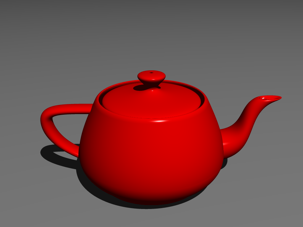 ![\includegraphics[width=0.45\textwidth]{teapot-256}](img22.png) |
Figure:
128 & 64 colors
![\includegraphics[width=0.45\textwidth]{teapot-128}](img23.png) ![\includegraphics[width=0.45\textwidth]{teapot-64}](img24.png) |
Figure:
32 & 16 colors
![\includegraphics[width=0.45\textwidth]{teapot-32}](img25.png) ![\includegraphics[width=0.45\textwidth]{teapot-16}](img26.png) |
Figure:
8 & 4 colors
![\includegraphics[width=0.45\textwidth]{teapot-8}](img27.png) ![\includegraphics[width=0.45\textwidth]{teapot-4}](img28.png) |
How can these logarithmically spaced intensity levels be displayed? According
to the formulas above the  -th level should have intensity
The intensity
-th level should have intensity
The intensity  of a CRT is proportional to
  , where
  is the
number of electrons and
is the
number of electrons and  is some constant depending on the phosphors used
in the CRT and is usually in the range
is some constant depending on the phosphors used
in the CRT and is usually in the range
 . Since the number
of electrons emitted is approximately proportional to the applied control-grid
voltage
. Since the number
of electrons emitted is approximately proportional to the applied control-grid
voltage  we have
 for some constant
So suppose the intensity
we want to display is . The corresponding index has to be chosen such that
 is as close to 1 as possible, i.e.
 . The
corresponding is thus
. The
corresponding is thus
 . If this
conversion is not hardcoded into the display, the software has to take account
on this. This is called GAMMA-CORRECTION. Without
gamma-correction quantization errors (produced by approximating true intensity
levels by discrete displayable ones) are more conspicuous near black than near
white.
. If this
conversion is not hardcoded into the display, the software has to take account
on this. This is called GAMMA-CORRECTION. Without
gamma-correction quantization errors (produced by approximating true intensity
levels by discrete displayable ones) are more conspicuous near black than near
white.
Andreas Kriegl 2003-07-23