Next: 5.1.9 Sor Up: 5.1 Solid Finite Objects Previous: 5.1.7 Interpolation and Splines
LATHE:
  lathe { [LATHE_SPLINE_TYPE] NUM_POINTS, POINT_LIST
    [LATHE_MODIFIERS] }

LATHE_SPLINE_TYPE:
  linear_spline | quadratic_spline | cubic_spline | bezier_spline

LATHE_MODIFIERS:
  [sturm [BOOL]] | [UV_MAPPING] | [OBJECT_MODIFIERS]
See also:
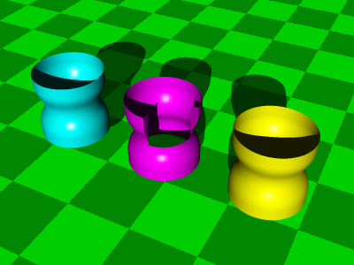
This describes an object obtained by rotating the area between the ![]() -axes and the spline
given by the NUM_POINTS many 2d-points in POINT_LIST around the
-axes and the spline
given by the NUM_POINTS many 2d-points in POINT_LIST around the ![]() -axes.
-axes.
For the spline type linear_spline we need NUM_POINTS![]() ,
and for the spline type
,
and for the spline type quadratic_spline
we need ![]() NUM_POINTS
NUM_POINTS![]() , where from
, where from ![]() to
to ![]() we use the quadratic spline constructed for
we use the quadratic spline constructed for
![]() .
Thus the curve will start only at
.
Thus the curve will start only at ![]() and end at
and end at ![]() , and
, and ![]() is just a control point.
is just a control point.
For cubic_splines we need ![]() NUM_POINTS
NUM_POINTS![]() , where
from
, where
from ![]() to
to ![]() we use the cubic spline constructed for
we use the cubic spline constructed for
![]() .
Thus the curve will start only at
.
Thus the curve will start only at ![]() and end at
and end at ![]() , and both
, and both ![]() and
and ![]() are
just control points.
are
just control points.
Finally for bezier_spline we need ![]() NUM_POINTS, where
we use the cubic Bezier curve through the points
NUM_POINTS, where
we use the cubic Bezier curve through the points
![]() from
from ![]() to
to
![]() .
Thus only the points
.
Thus only the points
![]() will ly on the curve, the others are just control points.
will ly on the curve, the others are just control points.
Andreas Kriegl 2003-07-23